64-channel
Fermionics, STURM2-based x-ray Monitor page
Design
(single place) documentation
Documentation
for ATF2
readout
64-channel motherboard: will bond out 64 Fermionics
elements.
Readout board reference documentation:
STURM2
NEW 2013 Design:
-- Updated 1 April 2015--
-- XRM Firmware Update --
Board Photographs
- Fermionics RevB [1]
- RF fanout RevA [1]
- IRSX DC RevA
[1]
- IRSX Carrier RevA
[1] [2] [3]
- Clock Fanout RevA
[1] [2]
- IRSX Motherboard RevA
[1] [2] [3]
- IRSX Hardware
[1]
[2]
- STURM2 & IRSX Hardware [1] [2] [3]
-------NEW XRM Design
------------------------------------------------------------------
- Short presentation
of the boards
- XRM Boards Timetable
- IDL_14_022_DC_IRSX_XRM_RevA
*
Schematic [Sch]
[PDF]
*
Layout [Pcb]
[PDF]
* BOM
- IDL_14_023_XRM_Motherboard_RevA
*
Schematic [Sch]
[PDF]
*
Layout [Pcb]
[PDF]
*
BOM
- IDL_14_024_XRM_CLK_Fanout_RevA
*
Schematic [Sch]
[PDF]
*
Layout [Pcb]
[PDF]
*
BOM
- IDL_14_025_IRSX_Carrier_RevA
*
Schematic [Sch]
[PDF]
*
Layout [Pcb]
[PDF]
* BOM
- Design Notes
- System Casign [PDF]
Latest desing files also at IDLAB
PCB Page
- Proposed
Power Supply for the system
- Casing
for the power Supply
-------------------------------------------------------------------------------------------------------------
PDF Presentation of
the new 2013 design
PDF presentation of the
system enclosure
Firmware &
software presentation
Beam Test Results
6/5/2014
-------ASIC Testing Results
---------------------------------------------------------------------------
- Dac outputs
- Test results PDF
-------STURM2 Firmware and
Software-------------------------------------------------------------
- Software
- Firmware
- UCF (26-APRIL-2014):
[.ucf]
- FPGA Pin definitions
[PDF]
------- IRS3C Firmware and
Software----------------------------------------------------------------
- Software
- Firmware (old)
- Firmware (JM
modified)
- Pin mapping (5-MAR-2014): [xls]
- UCF (5-MAR-2014): [.ucf]
-------------------------------------------------------------------------------------------------------------
1. Ferminonics sensor board REV A
1. Schematics
[sch]
[PDF]
2. Layout
[pcb]
[PDF]
3. PDF Presentation
4. Bill Of Materials
2. Ferminonics sensor board REV B
1. Schematics
[sch]
2. Layout
[pcb]
3. Bill
Of Materials
3. RF fanout board edgemount REV A
1. Schematics
[sch]
2. Layout
[pcb]
3 Bill Of
Materials
4. cables and connectors
XLSX
4. Amplifier board REV D
1. Schematics
[sch]
[PDF]
2. Layout
[pcb] [PDF]
3. PDF Presentation
4. Bill Of Materials
5. Amplifier power board REV A
1. Schematics
[sch]
[PDF]
2. Layout
[pcb]
[PDF]
3. PDF Presentation
4. Bill Of Materials
6. STURM2 DC board REV D
1. Schematics
[sch]
[PDF]
2. Layout
[pcb] [PDF]
3. PDF Presentation
4. Bill Of Materials
5. Changes
from REV C
7. DC / SCROD power board REV B
1. Schematics
[sch]
[PDF]
2. Layout
[pcb]
[PDF]
3. PDF Presentation
4. Bill Of Materials
5. Changes
from REV A
-------------------------------------------------------------------------------------------------------------
8. IRS3B Common DC Board
1. Schematics
[sch]
[PDF]
2. Layout
[pcb]
[PDF]
3. Bill
Of Materials
9. STURM2 Common DC Board
1. Schematics
[sch]
[PDF]
2. Layout
[pcb]
[PDF]
3. Bill
Of Materials
10. Common Power Board for STURM2 and IRS3B DC Boards
1. Schematics
[sch]
[PDF]
2. Layout
[pcb]
[PDF]
3. Bill
Of Materials
-------------------------------------------------------------------------------------------------------------
11. RF Signal splitter
1. Schematics
[sch]
[PDF]
2. Layout
[pcb]
[PDF]
12. Amplifier RF Shield PDF
1. RF Shield pictures 1 2
13. Ferminonics sensor / RF Connectors Pin Order
New Trace Impedance Calculator
OLD
VERSION
- STURM2 ASIC reference page [link]
- STURM2 ASIC bonding diagram [PDF]
- Amplifier Rev. B
- Test result summary [PDF]
- Preliminary test results [xlxs]
- Schematics [sch]
- Layout [pcb]
- Viewable w/o PADS [PDF]
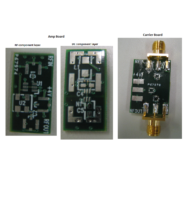
- Board
photograph
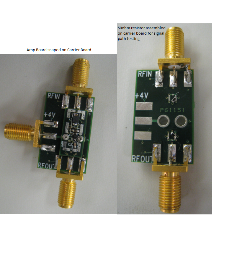
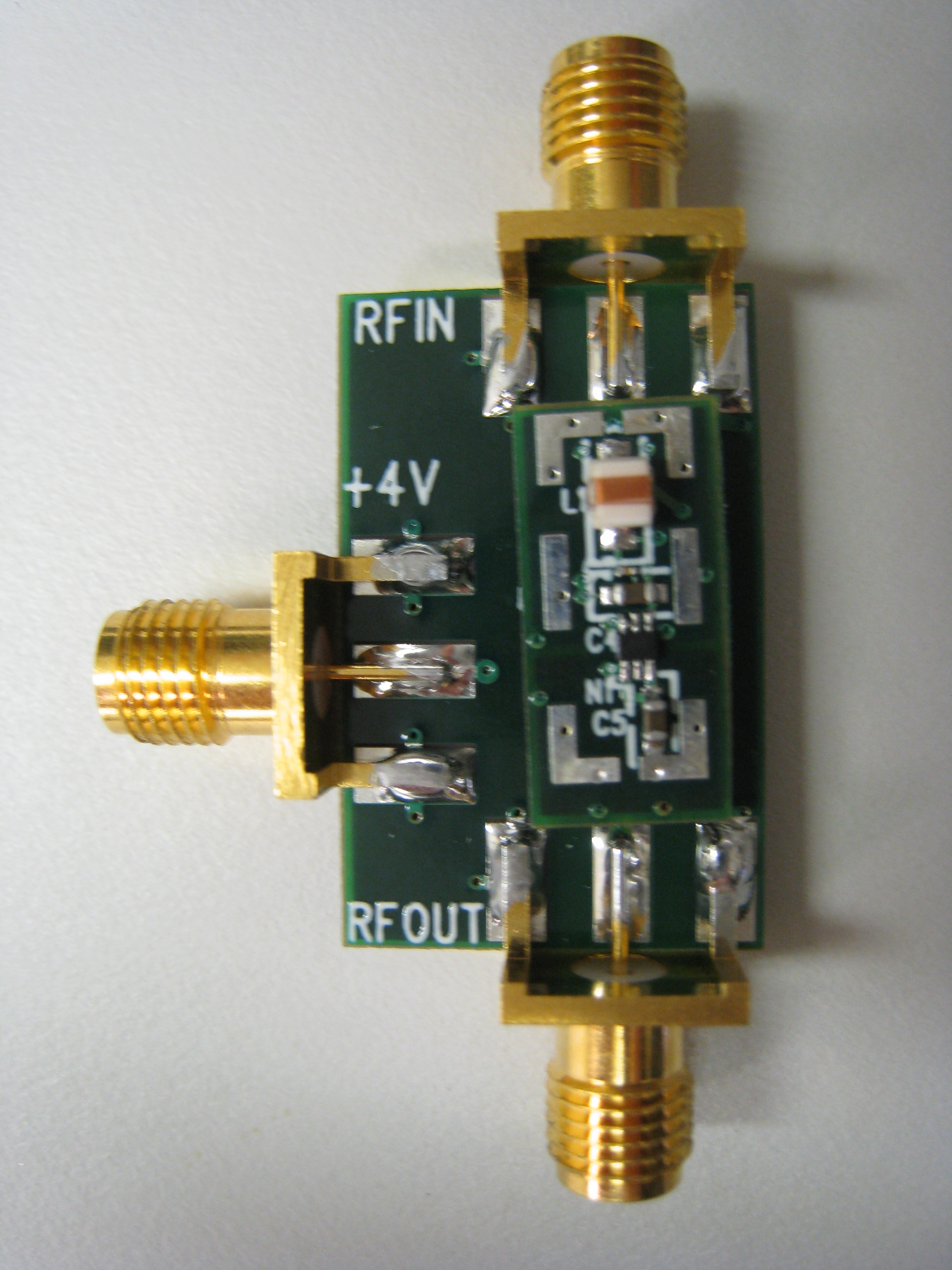
- Assembled Boards photograph
- Amplifier Rev. C -- (replace pins with same height connector for power)
- Schematics [sch]
[PDF]
- Layout [pcb]
[PDF]
- Carrier test board -- Rev. B (with same height
connector for power)
- Schematics [sch]
[PDF]
- Layout [pcb]
[PDF]
- Board
photogragh
- Assembled Boards photograph
- Carrier Boards
testing comparison
- Testing
results
- STURM2 ASIC carrier card
- Design
overview
- Schematics [sch]
- Layout [pcb] [PDF] (7/18/11 updated)
- AFT2 readout Motherboard
- Amp Gain
Derivation (60dB)
- Schematics [sch]
[PDF] ( 11/25/11 updated )
- Layout [pcb] [PDF] ( 11/25/11 updated )
- Bill Of
Materials (
10/20/11 updated )
- Motherboard
presentation ( 10/4/11 updated )
- SCROD reference documentation
- Fermionics carrier card
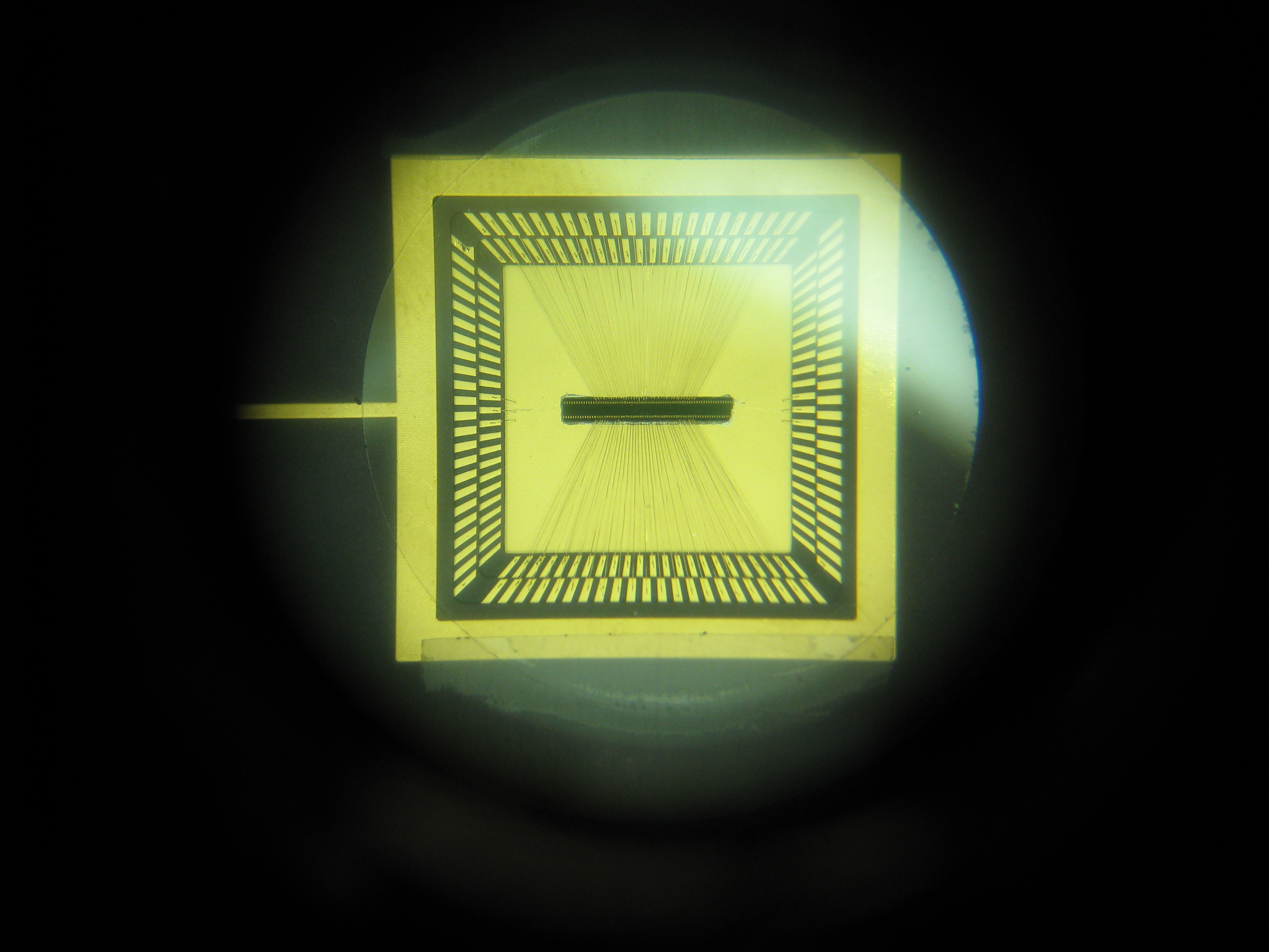
- Fermionics
sensor bonding diagram (7/20/11 updated)
- CPG18020
pin mapping (7/22/11
updated )
- Ferminonics
sensor pin order (7/22/11 updated )
- Fermionics
sensor picture (8/12/11 updated )
Return to scheduling page
[UH Physics] [University of Hawaii]
Last modified: 6/12/2014
-- GSV