|
Belle II KLM Scint Firmware
1
|
|
Belle II KLM Scint Firmware
1
|
Entities | |
| Behavioral | architecture |
Libraries | |
| IEEE | |
| unisim | |
| unimacro | |
| work | |
Use Clauses | |
| STD_LOGIC_1164 | |
| NUMERIC_STD | |
| STD_LOGIC_MISC | |
| STD_LOGIC_UNSIGNED | |
| vcomponents | |
| klm_scint_pkg | Package <klm_scint_pkg> |
Generics | |
| N_ASICS_g | integer := 10 |
| FORCE_TRIG_BUF_DEPTH_g | integer := 6 |
| TRG_BUFF_DEPTH_g | integer := 4 |
| TRIG_QUEUE_DEPTH_g | integer := 5 |
| TQ_PROG_FULL_THRESH_g | integer := 3 |
| CALC_ROI_LAG_g | integer := 2 |
| T_WAIT_2C_IF_QUEUE_FULL_g | integer := 31 |
| reset_buff_depth_g | integer := 10 |
| SLC_STAT_BUFF_DEPTH_g | integer := 4 |
| packet_type_g | std_logic_vector ( 7 downto 0 ) := X " 80 " |
| N_readout_samples_g | std_logic_vector ( 7 downto 0 ) := " 10000000 " |
| LAST_WINDOW_ADDRESS | std_logic_vector ( 8 downto 0 ) := " 111111111 " |
| N_BITS_AVG_g | integer := 7 |
| T_wait_busy_to_come_up_g | integer := 31 |
| FineLookback_win_g | std_logic_vector ( 8 downto 0 ) := " 000000001 " |
| max_proc_time_g | std_logic_vector ( 15 downto 0 ) := " 0011000110011100 " |
Ports | |
| clk | in std_logic := ' 0 ' |
| busy | out std_logic := ' 0 ' |
| b2tt_runreset | in std_logic := ' 0 ' |
| trig | in trig_info_type_0 := null_trig_info_t0 |
| ana_wr_ena_mask | out TARGETX_analong_wr_ena_mask_t := null_TX_ana_wr_ena_mask |
| localtrg | in std_logic := ' 0 ' |
| force_trig | in std_logic := ' 0 ' |
| sps_reset | in std_logic := ' 0 ' |
| cur_win | in std_logic_vector ( 8 downto 0 ) |
| qt_fifo_rd_en | in std_logic := ' 0 ' |
| daq data ports | |
| qt_fifo_dout | out std_logic_vector ( 17 downto 0 ) := ( others = > ' 0 ' ) |
| qt_fifo_empty | out std_logic := ' 1 ' |
| qt_fifo_err_cnt | out std_logic_vector ( 15 downto 0 ) |
| qt_fifo_evt_rdy | out std_logic := ' 0 ' |
| full_proc_cnt | out std_logic_vector ( 15 downto 0 ) := ( others = > ' 0 ' ) |
| simp_proc_cnt | out std_logic_vector ( 15 downto 0 ) := ( others = > ' 0 ' ) |
| null_proc_cnt | out std_logic_vector ( 15 downto 0 ) := ( others = > ' 0 ' ) |
| RAM_IO | inout std_logic_vector ( 7 downto 0 ) := ( others = > ' 0 ' ) |
| RAM_WEb | out std_logic := ' 1 ' |
| RAM_OEb | out std_logic := ' 0 ' |
| RAM_ADDR | out std_logic_vector ( 21 downto 0 ) := ( others = > ' 1 ' ) |
| BUSA_DO | in std_logic_vector ( 14 downto 0 ) := ( others = > ' 0 ' ) |
| BUSA_RAMP | out std_logic := ' 0 ' |
| BUSA_CLR | out std_logic := ' 0 ' |
| BUSA_RD_COLSEL | out std_logic_vector ( 5 downto 0 ) := ( others = > ' 0 ' ) |
| BUSA_RD_ENA | out std_logic := ' 0 ' |
| BUSA_RD_ROWSEL | out std_logic_vector ( 2 downto 0 ) := ( others = > ' 0 ' ) |
| BUSA_SAMPLESEL | out std_logic_vector ( 4 downto 0 ) := ( others = > ' 0 ' ) |
| BUSA_SR_CLEAR | out std_logic := ' 0 ' |
| BUSA_SR_SEL | out std_logic := ' 0 ' |
| BUSB_DO | in std_logic_vector ( 14 downto 0 ) := ( others = > ' 0 ' ) |
| BUSB_RAMP | out std_logic := ' 0 ' |
| BUSB_CLR | out std_logic := ' 0 ' |
| BUSB_RD_COLSEL | out std_logic_vector ( 5 downto 0 ) := ( others = > ' 0 ' ) |
| BUSB_RD_ENA | out std_logic := ' 0 ' |
| BUSB_RD_ROWSEL | out std_logic_vector ( 2 downto 0 ) := ( others = > ' 0 ' ) |
| BUSB_SAMPLESEL | out std_logic_vector ( 4 downto 0 ) := ( others = > ' 0 ' ) |
| BUSB_SR_CLEAR | out std_logic := ' 0 ' |
| BUSB_SR_SEL | out std_logic := ' 0 ' |
| SAMPLESEL_ANY | out std_logic_vector ( 9 downto 0 ) := ( others = > ' 0 ' ) |
| SR_CLOCK | out std_logic_vector ( 9 downto 0 ) := ( others = > ' 0 ' ) |
| wave_config | in wave_config_t := default_wave_config |
| wave_stat | out waveform_stat_t := wave_stat_0 |
| debug_wave_we | out std_logic_vector ( 1 downto 0 ) := ( others = > ' 0 ' ) |
| debug_wave_din | out slv12 ( 1 downto 0 ) := ( others = > ( others = > ' 0 ' ) ) |
| SPS_hist_rd_data | out slv16 ( 1 downto 0 ) := ( others = > ( others = > ' 0 ' ) ) |
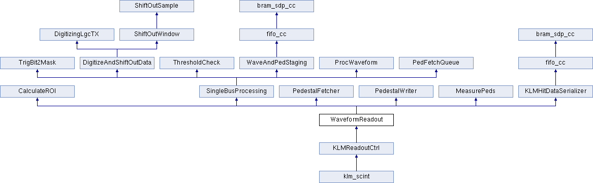
The job of this module is to manage all the modules needed for waveform readout, pedestal management, and feature extraction. When a local trigger is received, the region of interest is calculated and the trigger is put into the queue. If the queue gets too full, the next packets will be of the 'simple' type to speed things up, otherwise digitization will proceed
The FSM ro_states starts digitization and ultimately sends DAQ packets. Digitization and processing happens in parallel on both busses. This is taken care of by each SingleBusProcessing module. In each of these modules, TrigBit2Mask modules generate one channel mask for each ASIC on the bus. The module DigitizeAndShiftOutData begins digitizing the first window for all ASICs on the bus, and meanwhile, PedFetchQueue starts fetching pedestals for the hit channel which is first to be shifted out. The ped fetcher arbitrates which bus (A/B) gets RAM access first.
As digitization of the first window finishes, all channels on any hit ASICs shift out 32 samples** in parallel. ThresholdCheck writes all hit channels to their own deticated FIFO in WaveAndPedStaging while at the same time checking each channel to see if it crossed a programable threshold value. Digitization of the remaining windows in the ROI follows suit. When finished shifting out the last window, the new channel mask generated by ThresholdCheck is used to flush stale jobs from the PedFetchQueue and tell ProcWaveform which channels to process.
As ProcWaveform finishes its first job, it tries to send the results to ro_states. An arbiter prevents collisions in case both buses finish at the same time. ro_states keeps track of first hit, last hit, and resets all the FIFOs when the event is finished.
For pedestal measurement and writing, ped_sub_ena must be high, then force_trig initiates the process. MeasurePeds keeps an eye on the window counter and triggers readout only after it has passed. in this mode, the wave and ped FIFOs in WaveAndPedStaging are taken over and used to make a 24-bit wide summation. After 2**N_BITS_AVG_g dig cycles, the averaged pedestals are shifted out and written to SRAM
Lastly, two debug tools have been included in this firmeare. Debug waveforms are written to a fifo every time a waveform is processessed. This FIFO just fills up until somebody reads it from the register interface. The second is a histogram of charge measurements done using BRAM. It fills continuously until someone issues a reset
| Word | Word contents |
|---|---|
| 1 | type(2:0) / lane(4:0) / axis(0) / chnl(6:0) |
| 2 | ctime(15:0) |
| 3 | SIMP / TB5 / TDC(13:0) |
| 4 | TBD(3:0) / chg(11:0) |
Definition at line 70 of file WaveformReadout.vhd.
 1.8.13